A screen shot of the software in action.
|
electronics.alternatezone.com
Electronics related projects, information, and resources. |
|
| 40MHz 32 Channel Logic Analyser |
This project was published in Electronics Australia in Oct/Nov 96.
It is a 32 Channel, 40Mhz, fully PC controlled TTL/CMOS logic analyser with internal/external triggering and trigger delay. Internal triggering is fully maskable (High/Low/Don't Care) on all 32 channels. The whole things fits on one single sided PCB with virtually no wiring!
Unfortunately the PCLA is not available as a complete kit from any of the kit suppliers, and I no longer sell the pre-programmed PLD's. Only the software is available. So if you want to build it, then I'm afraid you'll have to make the PCB and program the PLD's yourself.
The PLD's were designed with the old Lattice Semiconductor ispLSI starter kit, but the newer Lattice development tools are available from the lattice web site. I have not used this new software, and email reports indicate that the files on this page are not compatible with it. I do not know how to solve this issue, so please don't ask. I have no plans to upgrade this project to new devices or software. The internal schematics for the chips are available on this page, you can use these to program the newer devices yourself.
NOTE : I get a *lot* of email about the ispLSI PLD chips in this project. For those of you who are unaware of what they are, they are Programmable Logic Devices, and they are BLANK when you buy them, you MUST program them with the JED files from here in order to get them to work. If you don't even know this much then you really have no need for this project!
I do NOT have the JED files for the LSI1016E, sorry.
Peter Baxter has developed a new Logic Anlyser product that should be on the market around the end of 2003. The delay is due to Business Partner issues, rather than engineering aspects. The earlier kit version completely sold out in 1999. There are no units available and no spare parts. You can look at the website: www.tantau.com.au/Files.html for info on the kit, but don't get excited by it. It is closed. The new one will be worth the wait.
If you want to see the Logic Analyser in action, check out Andrew March's home page
The PCLA software is now available for FREE for individual use, and is
provided as-is with no support.
I still hold complete copyright on the software.

A screen shot of the software in action.
View the Complete Article in text form.
View the Main Control & Interface Schematic.
View the Main Logic Circuit Schematic.
View the Control PLD Schematic.
View the Trigger PLD Schematic.
The Schematics in Protel format.
Download a complete working version of the Control Software, yes it's FREE for individual use!
Download the PCB file in Protel AutoTrax format.
View the PCB in 300dpi GIF format.
Download the PLD Files including the .JED and Lattice files. THESE ARE THE OLNY FILES I HAVE!
View the Component Overlay in GIF format.

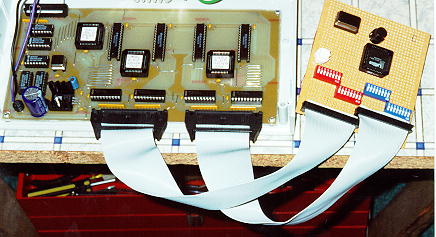
My first PCLA prototype with test pattern generator.
ERRATA
There is a problem with the timebase generation circuit that causes the 10MHz and lower ranges to be inaccurate. The basic problem is that the Q1 output of IC4 does not produce a 10MHz clock, but 8MHz instead, which causes all the ranges 10MHz and below to have an inaccurate timebase.
The only solution is to add an external 10MHz oscillator to replace the Q1 output from IC4.
Home - electronics.alternatezone.com
Copyright(c)1995-2003 David L. Jones